
VDA 450: Vehicle Power Distribution and Functional Safety – Part II
This article offers an in-depth look at topics related to Functional Safety and Electric Mobility. It continues from Part I of this series.
For expert-level training—including certification-based programs—on these topics and more, explore our Automotive trainings. To learn how we support product development, compliance, and organizational safety goals with consulting support, visit our Functional Safety & Cybersecurity and Electric Vehicle Development pages—or contact us directly.
1. VDA 450 Vehicle Power Distribution and Functional Safety
The evolution of road vehicles – driven by automation and electrification – may have slowed in pace, but it continues to advance steadily. Technologies like Advanced Driver Assistance Systems (ADAS) and Automated Driving Systems (ADS) are becoming more sophisticated, often integrating Artificial Intelligence (AI) to enhance performance and safety. These innovations are among the most discussed topics in the automotive industry today.
However, amid the excitement surrounding these cutting-edge technologies, one critical aspect often goes unnoticed: the power distribution infrastructure within the vehicle itself. This internal power supply is not just a convenience, it is a backbone to vehicle safety.
Traditional vehicle architectures rely on Fail-Passive safety mechanisms, where certain components can shut down in the event of a fault without violating any safety goals. This approach has been sufficient for conventional vehicles.
But with ADAS and ADS, the paradigm shifts. The vehicle must remain operational even in the presence of faults, meaning its critical functions must adhere to a Fail-Active design. Critical functions such as steering, braking, and lighting must continue to operate long enough for a driver to regain control or for the vehicle to perform a safety maneuver.
Take steer-by-wire technology, for instance. In a conventional vehicle, if power-assisted steering fails, the driver can still manually steer – albeit with increased effort. The vehicle remains controllable. In contrast, an autonomous system must maintain full control even in the event of a power failure.
This is where VDA 450 comes into play to ensure supply of power. It provides essential recommendations for building redundancy and independence into vehicle power sources and distribution systems. As the automotive industry moves toward higher levels of automation, ensuring a resilient and fail-operational power infrastructure is more critical than ever.
VDA 450 is a recommendation published by the VDA (‘Verband der Automobilindustrie’ which is the German Association of the Automotive Industry) and can be purchased here.
2. How this Blog is Organized
The blog outlines how functional safety principles – including redundancy, monitoring, power prioritization, and freedom from interference – are critical in the design and validation of EBN systems for modern vehicles, particularly those with automated driving capabilities.
In Part I of this short blog series, “VDA 450 Vehicle Power and FuSa – LV Net Voltages“, we discussed how VDA 450 eliminates uncertainty by defining LV net voltage ranges.
Before diving into the details, let’s define some key abbreviations used throughout this blog:
| Abbreviation | Meaning |
|---|---|
| ATV | Active Separating and Connecting Elements |
| EBN | Refers to the vehicle’s electrical power supply system, derived from the German term Energiebordnetz (“onboard energy net”). |
| FFI | Freedom From Interference – a concept from ISO 26262 ensuring that safety-related operations remain sufficiently independent from lower or non-safety functions. |
| FSR | Functional Safety Requirement – a term in ISO 26262 representing requirements derived from safety goals but abstracted from technical implementation. |
| FuSa | Functional Safety – in this context, it refers to automotive functional safety as defined by ISO 26262. |
| MRM | Minimal Risk Maneuver. Procedure performed by automated driving systems to place the vehicle in a minimal risk condition in a manner that avoids unreasonable risks in traffic. |
| SR | Safety-related |
| SR function | Safety-related function. Subfunction of the SR vehicle function (such as braking, steering, perception) which places safety requirements on the power supply. |
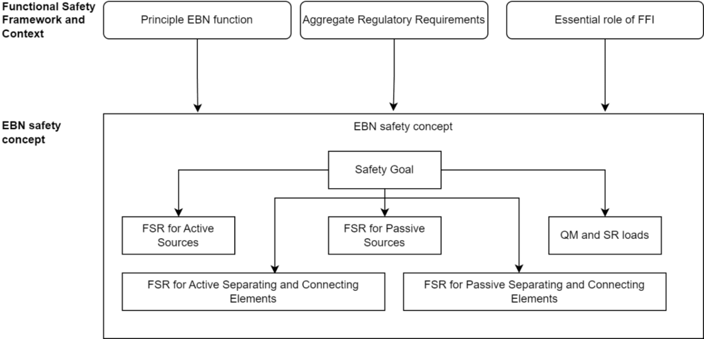
As shown in the figure below, the VDA 450 structure can be categorized into two main sections:
- Functional Safety Framework and Context
- a. EBN Classification in the ISO 26262 context
- b. Principle EBN function
- c. Aggregate Regulatory Requirements
- d. Essential Role of FFI
- EBN Safety Concept
- a. Safety Goal
- b. FSRs for power elements in the EBN
3. Functional Safety Framework and Context
3.1 EBN Classification in the ISO 26262 context
The vehicle’s power distribution network – referred to as the EBN (from the German term Energiebordnetz) – can be classified using various ISO 26262 terms: Item, System, Subsystem, or Element.
ISO 26262 Part 1 defines an Item as a “system […] that implements a function […] at the vehicle level.” In contrast, an Element is defined more broadly as a “system, component, hardware part, or software unit.”
This raises a key question: Does the EBN fulfill a vehicle-level function? Classic examples of vehicle-level functions include steering, braking, and accelerating. In other words, should power supply and distribution be seen as its own standalone function within the vehicle, or merely as a supporting part of other functions?
EBN as Item or System
As a typical supplier of an automotive system, I only use the power provided by the EBN – I have no responsibility for its distribution design. This clear separation of responsibilities between the EBN and the load supports the argument for treating the EBN as an independent entity within the vehicle architecture. Considering the EBN as an Item allows for bundling all power distribution-related requirements under a single functional umbrella.
EBN as Subsystem or Element
On the other hand, some argue that power distribution is not a vehicle function in itself. Instead, the EBN should be viewed as implicit part of vehicle functions like braking, accelerating, or steering. However, as stated above, this means we’re allocating power distribution requirements to systems that inherently have no responsibility in the power distribution.
3.2 Principle EBN Function
As defined in VDA 450 the EBN has the following primary functions:
- The EBN provides safety-related (SR) functions with sufficient power and energy
- EBN must be implemented so that SR maneuvers can be started, executed, and completed even in case of a fault. Non-SR maneuvers can be inhibited
From a vehicle availability perspective, all vehicle functions must receive adequate power and energy. However, from a FuSa standpoint, the focus is exclusively on ensuring that SR functions maintain operational integrity.
The requirement to support SR maneuvers even in the presence of a fault has significant implications for system design, particularly with regard to redundancy.
3.3 VDA’s 450 Aggregate Regulatory Requirements
VDA 450 provides an overview of both current and anticipated regulatory requirements relevant to power distribution in vehicles. The most pertinent regulations for aggregate EBN requirements include:
- UNECE R79 – Steering systems
- UNECE R13 – Braking systems
- UNECE R157 – Automated lane keeping assist systems (ALKS)
EBN-FR 1: The EBN shall monitor its status and report it to Higher-Level Instances and/or the driver
For example, any under- or overvoltage conditions must be detected and reported. A Higher-Level instance refers to a vehicle unit responsible for processing warnings and diagnostic data. It determines and coordinates fault responses, especially for Automated Driving Systems (ADS).
Status monitoring does not necessarily require additional dedicated hardware. This functionality may be distributed across existing systems – such as the Battery Management System (BMS) or loads capable of measuring their supply voltage and reporting diagnostics.
EBN-FR 2: The EBN shall provide at least two independent energy storage devices and transmission channels to supply the SR-Function Brake
This requirement originates from UNECE R13, which mandates redundancy for braking. However, similar redundancy considerations should apply to steering and other SR functions for automated driving.
EBN-FR 3: An overlap of different functions such as steering, braking, light, visibility and drive functions shall be taken into consideration
This requirement primarily addresses the dimensioning of the EBN, especially in scenarios involving braking and steering maneuvers. For example, UNECE R79 specifies that the system must continue operating even with an energy source fault. Ensuring that other critical systems (e.g. lighting and braking) remain functional is essential for maintaining vehicle safety.
Additional requirements emphasize the EBN’s ability to prioritize power delivery to SR functions – especially braking and steering – by restricting power to non-critical loads when necessary.
Finally, VDA 450 mandates that the design and development of power supplies for SR loads must, at a minimum, consider ISO 26262 standards for functional safety.
3.4 Essential Role of Freedom From Interference
Freedom from interference (FFI) is a foundational concept for ensuring non-safety functions do not interfere with safety-related functions or between safety functions of different ASIL. Within the context of the EBN, FFI must be considered for both the power sources and the channels that deliver energy to the loads.
- FFI for EBN power sources
The requirement for sufficient power is typically decomposed into active sources (e.g., DC/DC converters) and passive sources (e.g., batteries). Each source must independently be capable of providing enough energy to support the execution of SR maneuvers in the absence of the other.
If a power source is dependent on mechanical input from the drivetrain, its output is generally only considered QM (Quality Management) and may not be suitable for safety-related redundancy.
- FFI for EBN channels
Independence must also extend to the EBN channel – the entire electrical path from the energy source to the load. For instance, if a fault occurs (e.g., a failed contactor or a corroded connector), a second, fully independent channel must be available to continue supplying the load.
This includes not just the physical wiring, but also the electronic components used for power distribution and interruption. Note that homogeneous redundancy – using identical electronic systems on both channels – can pose challenges for safety decomposition due to shared failure modes.
- FFI for loads
While FFI focusses mostly on the power sources and channels, FFI for EBN channels has implications for the SR load itself – for example, it must be capable of operating on any single supply and maintaining independence between channels. For example, let’s say one channel lost power and an SR load operates using the redundant channel. The load must not divert power from the working channel into the non-working channel.
While FFI primarily addresses power sources and distribution channels, it also has implications for SR loads. Each SR load must be capable of operating from a single power channel in the event of a fault and must preserve channel independence.
For example, if one channel fails and the load continues to operate on the redundant channel, the load must not inadvertently backfeed or transfer power into the non-functioning channel. This ensures electrical separation and prevents fault propagation between redundant paths.
4. EBN Safety Concept
4.1 SR Function, SR Maneuver, and MRM
In the context of the EBN, a Safety-Relevant (SR) function refers to any vehicle function with safety requirements tied to the power supply. This includes critical systems such as braking, steering, and perception – all of which must be reliably powered to maintain vehicle safety.
An SR maneuver is a vehicle-level driving action performed to avoid hazards – such as evasive steering to avoid a collision or safely passing pedestrians on a rural road. These maneuvers require full availability of SR functions and reliable power supply.
A Minimal Risk Maneuver (MRM) brings the vehicle to a safe state that avoids unreasonable risk to traffic participants. Executing an MRM typically requires fail-operational capability, meaning the vehicle must continue functioning safely even in the presence of certain faults – this implies the need for system redundancy and robust EBN design.
An MRM is a subset of SR maneuvers.
4.2 EBN FSRs
Classifying the EBN as an Item, we can assume the following FSRs:
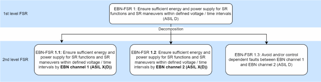
VDA 450’s Functional Safety Requirements (FSRs) focus specifically on securing the power supply.
4.3 TSRs for Elements and Components
4.3.1 FSR and TSR Delineation in VDA 450
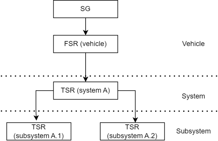
VDA 450 defines safety requirements for elements and components using the term Functional Safety Requirements (FSRs). However, from a strict ISO 26262 perspective, these requirements may be more accurately classified as Technical Safety Requirements (TSRs).
According to ISO 26262:2018 (Part 8, Figure 2 and Part 4, Figure 3), FSRs are derived from the safety goals at the vehicle level, whereas TSRs are allocated at the system level and can be further refined for subsystems and components.
Therefore, while VDA 450 uses the term FSR, many of the listed requirements for components and subsystems would technically fall under the scope of TSRs in ISO 26262 terminology.
4.3.2 Overview
VDA 450 categorizes the systems connected to the EBN into three main groups: sources, power distribution, and loads. These systems either provide power, distribute it, or consume it.
Power Sources
- Active Sources: Generators, DC/DC converters
- Passive Sources: Batteries, capacitors
- Energy Management Units
Power Distribution
- Active Separating and Connecting Elements (ATV): DC/DC converters, relays, semiconductor switches
- Passive Separating and Connecting Elements: Wires, connectors, passive fuses, screw terminals
Loads
- QM Loads (non-safety-critical)
- SR Loads Safety-relevant (ASIL-classified)
VDA 450 provides detailed FSRs for each component type, addressing the delivery of power to safety-related components. Key safety topics include:
- Ensuring and monitoring the power supply
- Detecting and reacting to under- and overvoltage conditions
- Preventing power delivery in case of detected short circuits
- Limiting unintended energy flow to ground
- Enabling controlled power degradation
4.3.3 TSRs for Active Sources
As an example – find the VDA 450 safety requirements for the Active Sources (AQ) in detail.
We will use the VDA FSR-based reference with the awareness that they should be considered as TSRs.
Active sources – such as generators and DC/DC converters – are subject to safety requirements to ensure they reliably provide power to SR functions:
- AQ-FSR 1: The AQ shall supply a defined power when the operation of an SR-Vehicle-Function for a defined duration.
- AQ-FSR 2: The AQ shall monitor its ability to supply the required power to SR-Functions. The AQ shall predict restriction in the power feed (e.g. thermal derating) and notify the Higher-Level Instance.
- AQ-FSR 3: The AQ shall restrict power consumption if notified that SR functions are being exercised.
- AQ-FSR 4: The AQ shall prevent overvoltage at SR interface caused by AQ internal faults.
- AQ-FSR 5: The AQ shall prevent undervoltage SR interface caused by AQ internal faults.
- AQ-FSR 6: The AQ shall not generate an output frequency or amplitude outside of the specified range.
5. EBN Topology
Finally, let’s look at a EBN topology example:
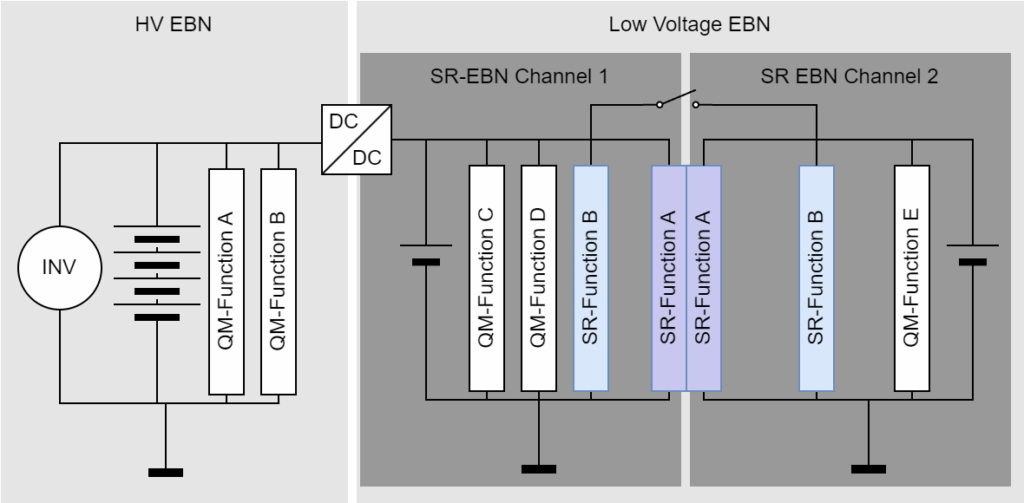
This illustrative topology includes one high-voltage (HV) channel and two low-voltage (LV) SR-EBN channels (Channel 1 and Channel 2), which are separated by an ATV.
Each LV channel is supported by its own passive energy source, providing mutual backup in case of a fault. Additionally, a DC/DC converter acts as an active power source, converting high-voltage energy into low-voltage supply, further enhancing redundancy and flexibility.
Two SR-Functions – Function A and Function B – are distributed across the two SR-EBN channels to ensure functional separation and fault tolerance.
For simplicity, the traction inverter is shown here as a QM component. However, in an actual vehicle application, the inverter would typically be classified as an SR-Function, incorporating both high-voltage and low-voltage domains.
6. Blog Summary
This blog explores the functional safety concept of the vehicle’s power distribution network (EBN), as outlined in VDA 450 and relevant in context of the ISO 26262 standard. The EBN is responsible for reliably supplying power to safety-relevant (SR) vehicle functions—particularly those involved in automated driving systems (ADS).
Key Topics Covered:
- EBN Functional Role:
- Ensures sufficient power and energy supply to SR functions, even in the presence of faults.
- Enables the safe execution of SR maneuvers, while non-SR maneuvers may be inhibited.
- System Classification Debate:
- Discusses whether the EBN should be classified as an Item, System, Subsystem, or Element under ISO 26262.
- Supports treating EBN as a distinct system due to its clear design and responsibility separation from the loads it supplies.
- Regulatory Requirements (VDA 450 & UNECE):
- Highlights key functional safety requirements mainly based on UNECE R13 (braking), R79 (steering), and R157 (ALKS).
- Emphasizes monitoring, redundancy, prioritization of SR loads, and dimensioning for overlapping functions.
- Freedom from Interference (FFI):
- Explains the need for FFI at both the power source and channel levels.
- Requires full independence between redundant paths to prevent common failure modes.
- EBN Safety Concept
- Outlines EBN FSRs
- Summarizes TSRs for EBN components and elements
- Details TSRs for active sources (e.g., DC/DC converters)
- EBN Topology Example:
- Presents a conceptual topology with two redundant SR-EBN LV channels, supported by both passive and active power sources.
- Demonstrates separation of SR functions and the inclusion of a high-voltage to low-voltage DC/DC conversion path.