
SW-FMEA Example
This article offers an in-depth look at topics related to Functional Safety. It continues from Part I of this series: Is the SW-FMEA Busy-work? – A SW-FMEA guide. The previous blog will now be referred to as SW-FMEA guide.
For expert-level training—including certification-based programs—on these topics and more, explore our Automotive trainings. To learn how we support product development, compliance, and organizational safety goals with consulting support, visit our Functional Safety & Cybersecurity page—or contact us directly.
1. Introduction
The purpose of the SW-FMEA is to systematically and comprehensively evaluate the safety-related software architecture and its functions.
Let’s reflect on key differences between the commonly known FMEA (DFMEA, PFMEA) and the SW-FMEA
- No RPN (Risk Priority Number). Unlike traditional FMEAs, the SW-FMEA in this blog does not include severity, occurrence, and detection ratings. The SW-FMEA Guide discusses the possibility of using occurrence and detection numbers as risk judgments, but their value is debatable and thus not utilized.
- No Root Cause Analysis. In SW-FMEA, the only root cause is “bugs.” Therefore, traditional root cause analysis might not be necessary.
- Mental Model for Evaluating Potential Malfunctions. A structured mental model is employed to assess the local and system-level effects of malfunctions.
2. Pre-requisites
SW-FMEA is a part of safety-oriented software analysis and interacts with software architecture and safety requirements, as illustrated in the figure below.
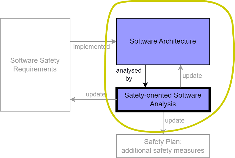
The primary input to SW-FMEA is the software architecture, which includes static and dynamic aspects.
Static architecture
- Software layers
- Software distribution across cores and OS threads
- Software block diagram: Functional software modules with ASIL ratings and their interfaces to hardware or boundaries to different ASIL
- Memory layout (ROM, RAM)
Dynamic architecture
- Interrupt and scheduler timings
- Communication busses (external and within the product)
A software block diagram is typically sufficient for the SW-FMEA. For complex software, multiple diagrams at different abstraction levels may be required.
Identified gaps lead to corrective actions such as enhancing safety requirements, modifying the software architecture, or adding safety measures.
3. Inverter Example Architecture
3.1 Software Safety Requirement Example
Let’s assume an ASIL C safety goal of preventing unintended acceleration or deceleration for a traction inverter in an electric drive powertrain.
The defined safe state is active 3-phase short, which involves shorting the motor coils to each other to prevent overvoltage on the DC voltage rail.
Example of a Software Safety Requirement:
If the torque output exceeds TORQUE_REQUEST ± ACCEPTABLE_RANGE_THRESHOLD Nm for more than PERCEPTION_THRESHOLD ms, the system shall trigger a safe state request.
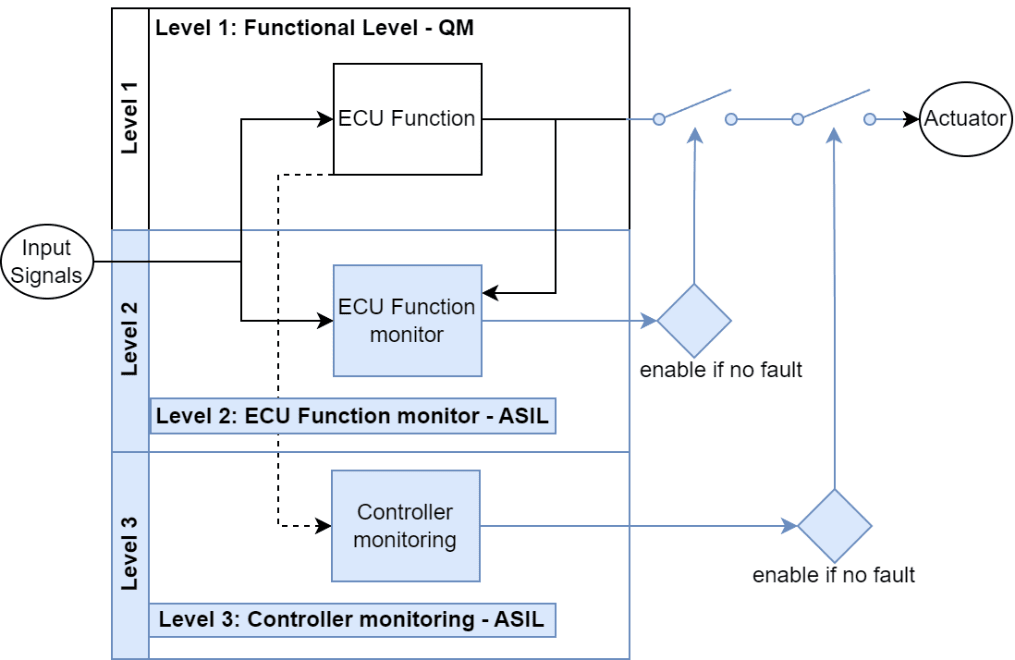
3.2 E-gas design pattern
The E-Gas structure is a well-established trusted design architecture for inverters. It separates nominal functions from safety functions, allowing for advantages such as easier updates to nominal functions without compromising safety mechanisms.
It is important to note that the E-Gas principle fundamentally applies to fail-safe systems – systems where turning off or ceasing operation results in a safe state. In contrast, fail-operational systems must continue functioning to maintain safety even in the presence of a failure.
A traction inverter is generally considered fail-safe, as shutting it down can prevent hazardous situations. However, certain fail-operational aspects exist, such as 3-phase short, which requires parts of the control logic and inverter power stage to remain at least partially operational to ensure system safety.
E-gas consists of three levels:
- L1 (Nominal Function): Contains the most software complexity. As L1 functions are QM, they fundamentally don’t require a SW-FMEA. However, the confirmation of which parts of the software are safety-related parts is very much part of the SW-FMEA.
- L2 (Function Monitoring): Ensures that L1 does not violate safety goals. If a violation occurs, a safe state is triggered. L2 has its own software architecture and is ASIL-rated, making it a target for SW-FMEA.
- L3 (Controller Monitoring): Verifies correct microcontroller functionality using features like BIST (Built-In Self-Tests), RAM, ROM, and stack tests. While L3 is safety-related, most functions are covered by hardware, requiring only configuration, activation, and service functions. SW-FMEA typically does not include L3 aspects. There are some exceptions that require deliberate architecture considerations such as when designing a safety operating system.
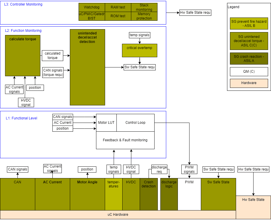
3.3 Inverter Software Architecture
The inverter software architecture is structured as follows:
- L1 receives a torque request and outputs actuator control signals to produce torque.
- L2 monitors L1’s output and triggers a safe state if the values exceed a safe range.
- L2 uses the same sensor inputs as L1, meaning sensor signals must be qualified to the according ASIL with measures like range checks, plausibility checks, or redundancies.
- L1 can use qualified sensor signals as long as it does not interfere with L2 functionality (confirmed via DFA, Dependent Failure Analysis).
4. Mental Model
Software can only exhibit systematic failures as per ISO 26262. The only failure possible in software is a “bug”, meaning coding error or design insufficiency, introduced during development. When a bug is found, the root cause must be addressed, and corrective actions taken. However, speculating about root causes in the SW-FMEA is unnecessary. That said, design changes or additional safety measures resulting from the SW-FMEA may require a root cause investigation. For example, additional safety measures to ensure transmission of safety signal over a bus might require a root cause analysis of an existing high bus load.
A historical example is NASA’s Mars Climate Orbiter, which was lost in 1998 due to a software bug that failed to correctly convert imperial to metric units. This exemplifies how a small software error can lead to catastrophic results. Fault tolerance means to continue to deliver a function in the presence of faults for fail-operational systems. Even if the metric unit is wrong, a hazardous event needs to be prevented.
The SW-FMEA focuses on ensuring robustness against erroneous inputs and fault tolerance . Instead of analyzing why a bug exists, we evaluate how the system handles incorrect signals and whether redundancies or plausibility checks are needed. For example:
- Effect: What is the impact of a potential malfunction?
- Mitigation (= safety mechanism or safety measure):
- Can we accept the risk of the resulting system level effect?
- Is there another signal that allows us to determine the received signal might be wrong?
- Do we need to implement additional measures such as a redundancy or plausibility check?
The following table proposes guidewords to be used for possible malfunctions. The essence of the guidewords is to provide a model of categorizing malfunctions irrespective of their actual root cause.
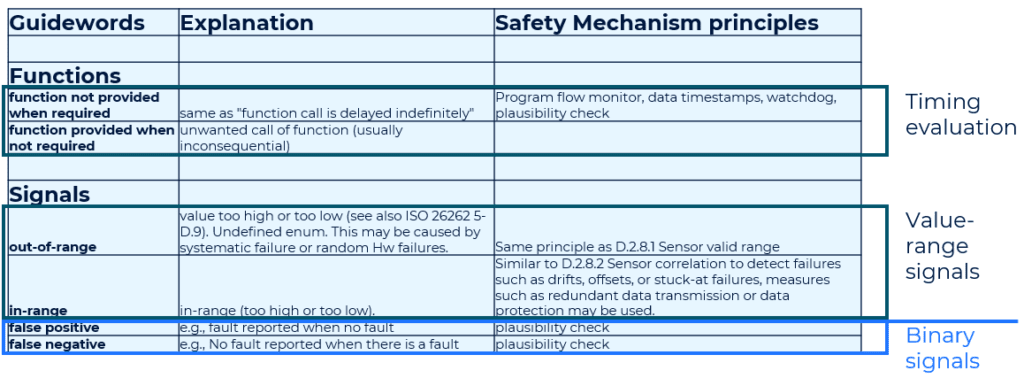
Timing-related aspects are allocated to function calls, while signal errors are analyzed using the following fault model inspired by hardware fault categories in ISO 26262 part 5.
5. SW-FMEA Example
This section contains multiple screenshots of an SW-FMEA against the software architecture shown in section 3.2.
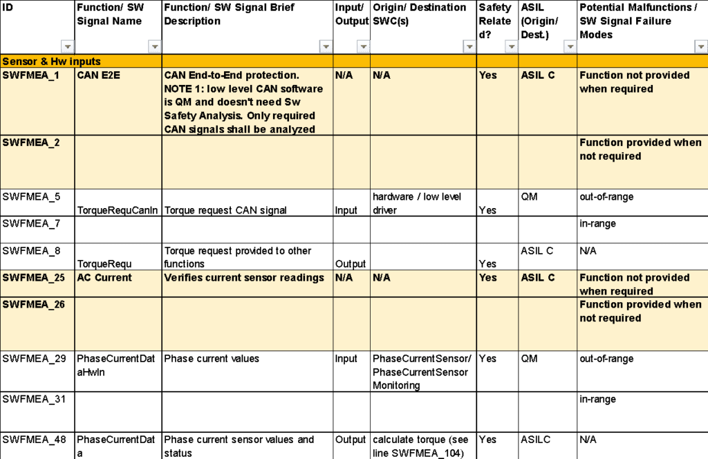
The below snippet shows the first SW-FMEA columns for the functions ‘CAN E2E’ and ‘AC Current’. Both functions are part of the module ‘Sensor & Hw inputs’. The functions qualify signals coming from the hardware to ASIL C signals.
The column ‘Potential Malfunctions’ contains the elements from the mental model explained in the previous section.
The SW-FMEA is continued in the next screenshot showing potential malfunctions, effects, and safety mechanisms.
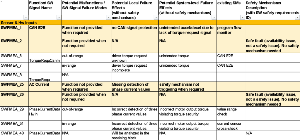
The program flow monitor ensures correct execution sequence and duration of the monitored functions. A minimum and maximum execution duration is defined for each function.
CAN E2E refers to the end-to-end protection of the communication on the CAN Bus. This includes CAN message CRC (in principle similar to a checksum), CAN sequence counter, CAN timeout, CAN value range check.
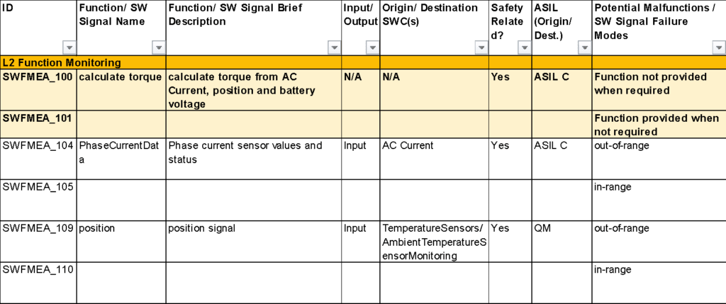
As an SW-FMEA example of another function, the next screenshot shows ‘calculate torque’ of the module ‘L2 Function Monitoring’
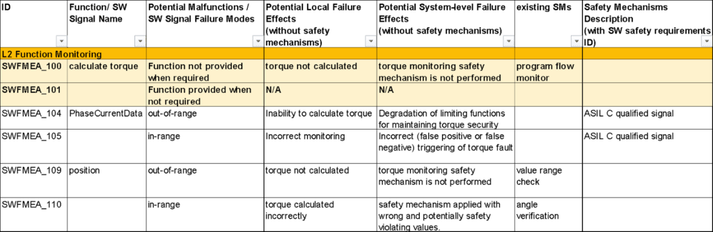
Signals previously qualified to the appropriate ASIL level can be used within the same software without another plausibility check, i.e. if one function stores a value in memory, then another function in the same software context can read it without another range or plausibility check as long as Freedom From Interference is ensured.
6. Ready to Perform an SW-FMEA?
If you’re ready to conduct an SW-FMEA but need additional support, resources, or expert assistance, contact us at SRES!